
German research team achieves ultra-compact plasma photocathode injection
 Scan to share
A research team from institutions including the Helmholtz-Zentrum Dresden-Rossendorf in Germany has demonstrated an ultra-compact plasma photocathode injection scheme integrated into a hybrid plasma wakefield accelerator on the DRACO laser facility. The study utilized a 150 TW-class laser system to drive a laser wakefield accelerator (LWFA), generating high-peak-current electron beams, which in turn drove a subsequent particle beam wakefield accelerator (PWFA), completing the generation and acceleration of witness electron beams within millimeter-scale plasma structures.
Plasma wakefield accelerators can produce accelerating fields far exceeding those of conventional radiofrequency linear accelerators, but how to obtain high-quality, high-brightness electron beams in compact devices has long been a key challenge for applications such as free-electron lasers. Plasma photocathode technology releases electrons inside the plasma wave via synchronized laser pulses, allowing these electrons to be rapidly captured, focused, and accelerated, potentially significantly improving beam quality.
In the experiment, researchers used a 3-mm-long laser wakefield acceleration stage to generate relativistic electron beams, with a thin foil blocking the spent laser pulse. The electron beam then entered another 3-mm-long PWFA stage. This stage employed a 50/50 hydrogen-helium gas mixture at a density of approximately 1.15×10¹⁸ cm⁻³, with a pre-ionization laser first forming a plasma channel. A third laser pulse was injected at a 90° angle to ionize the second ionization level electrons of helium, triggering the plasma photocathode process.
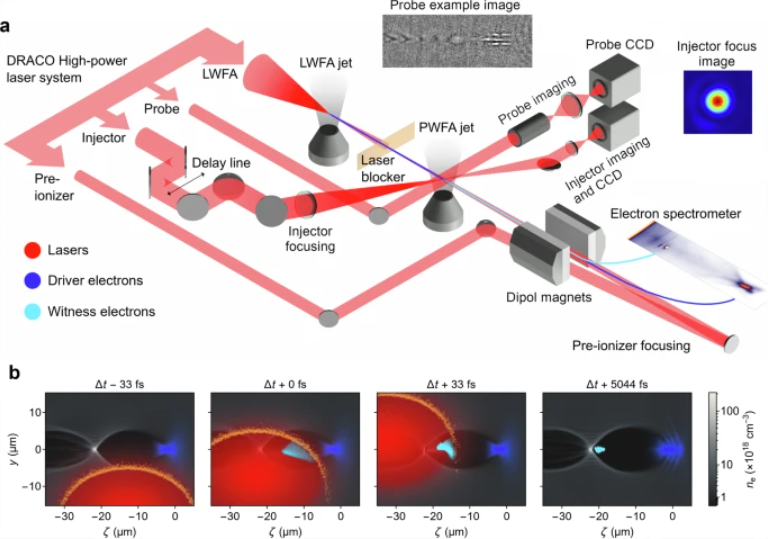
a Overview of the experimental setup. All lasers (red) originate from the DRACO laser source. The LWFA laser produces an electron beam in the LWFA jet and is blocked by a laser-blocking foil (orange). The resulting electron beam (dark blue) then propagates to the PWFA stage, which has been ionized by the pre-ionization laser. The injector produces the probe beam (light blue), which is recorded together with the drive beam by the electron spectrometer. The right inset shows an image of the injector focus. A probe beam is used to observe the interaction, with an example image shown in the upper inset. b Snapshot from particle-in-cell simulations illustrating the injection process, where ζ is the propagation axis coordinate in the co-moving frame. The electron beam (dark blue) drives a plasma wave in the blowout regime, and the ionization front (orange) of the injector laser pulse (red) ionizes He²⁺ as it sweeps through the plasma cavity. The He 2+ electrons (light blue) released at the center of the plasma wave are then rapidly compressed, captured, and accelerated within the plasma wave, forming the witness beam.
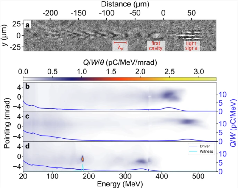
a. Shadowgraph of the injection point, showing the plasma wake within the PWFA stage. b. Electron beam spectrum from the LWFA with the blocking tape. c. Electron beam spectrum from the LWFA including the PWFA stage and blocking tape, but without the injector laser. d. Electron beam spectrum from the LWFA including the PWFA stage, blocking tape, and injector laser, resulting in a clear witness beam. The lines correspond to the spectral charge density of the indicated beams.
The experimental results show that when precise spatiotemporal overlap between the injector laser and the electron drive beam is achieved, the system produces a clearly distinguishable witness electron beam. The measured witness beam had a charge of approximately 10.7 pC within the full width at quarter maximum, an RMS divergence of 0.59 mrad, an RMS energy spread of 1.24 MeV, a mean energy of 183.1 MeV, and a relative energy spread of approximately 0.68%. The study also observed witness beams with energies exceeding 250 MeV, corresponding to accelerating field gradients on the order of approximately 100 GV/m.
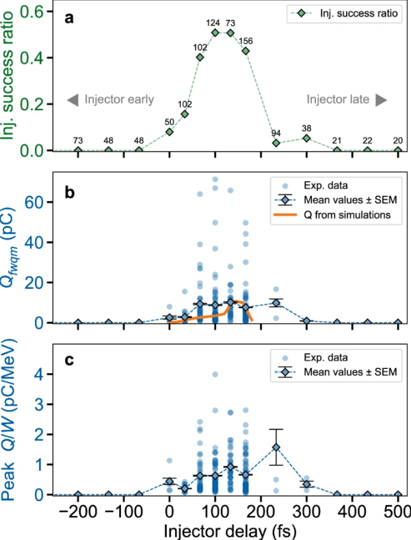
a. Experimentally observed injection success rate, with the total number of pulses at each delay time shown above the data points. b. Charge of the experimentally injected witness beam and the charge observed in simulations. c. Spectral charge density of the injected witness beam. Individual pulses are plotted with lower transparency to indicate the clustering of charge values. For each time point, the mean ± standard error of the mean (SEM) of the witness parameters is shown, with the number of witness beams analyzed being N = 4, 16, 41, 63, 37, 67, 3, and 2 (for delay times from 0 fs to 300 fs, respectively). Delay time 0 fs is defined as the earliest time point at which a witness beam is observed.
The research team further verified the injection mechanism through delay scans. The witness beam appeared only within a specific time window; when the helium injection target was removed or the injector laser path was blocked, no witness beam was observed. This indicates that witness beam generation depends on selective laser-triggered ionization and precise spatiotemporal alignment, consistent with the characteristics of plasma photocathode injection.
However, the experiments also revealed significant pulse-to-pulse fluctuations in witness beam parameters. Shadowgraph imaging analysis indicated that these fluctuations are related to factors such as drive electron beam charge fluctuations, variations in the degree of pre-ionization, and elongation of the first plasma cavity. The researchers believe that future improvements in laser wakefield accelerator stability, optimization of laser spatiotemporal characteristics, and the development of more precise diagnostic methods could enhance experimental repeatability and further characterize key beam parameters such as slice emittance and slice energy spread.
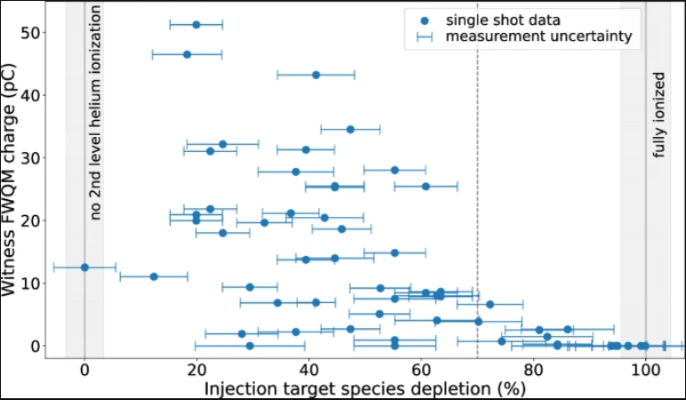
An additional dataset beyond those shown in the figure, in which the correlation between witness beam charge and ionization of injected target particles was determined through shadowgraph analysis. The gray lines represent the limits of 0% and 100% loss of injected target particles, with the width of the shaded region indicating the uncertainty. Error bars are defined by the uncertainty in cavity length measurement (precision of two pixels) divided by the number of cavities used to determine the depletion wavelength, and are determined individually for each measurement (N = 1). The additional dashed vertical line marked at 70% depletion references the operating point of the simulation studies shown in Fig. 3b) and in Supplementary Notes 6 and Supplementary Figs. 2, 4 .
This study demonstrates that high-density plasma photocathodes can be realized in compact all-optical setups, compressing part of the plasma photocathode research that traditionally requires kilometer-scale facilities onto meter-scale experimental platforms. The research team believes that this progress provides a new technical pathway for generating ultra-high-brightness electron beams and developing compact X-ray free-electron lasers for scientific applications.
Disclaimer: Information republished from partner media, institutions or other websites is provided for reference and communication purposes only. It does not imply endorsement of its views or verification of its accuracy. Please contact us if any content infringes rights or requires correction.